Imaging System and Optics
Overview
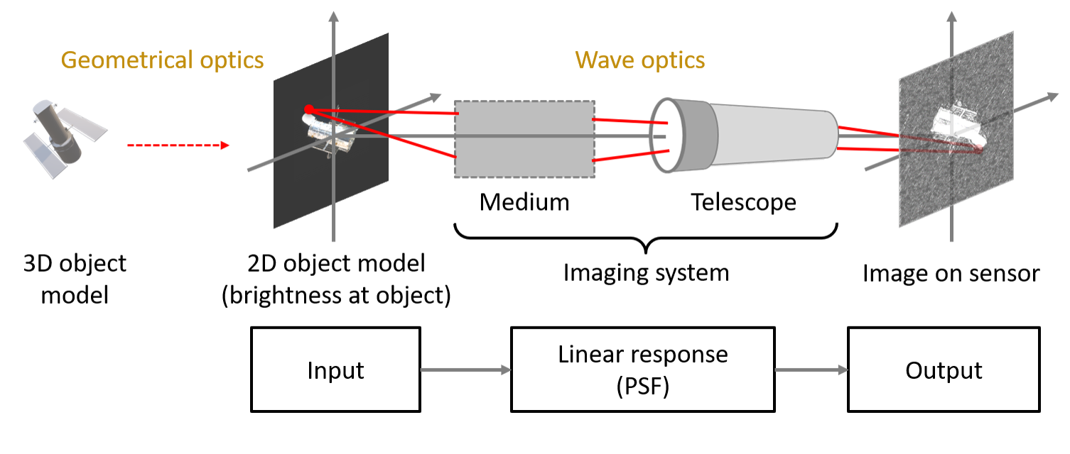
Optical images of a space object is modeled as a linear response of an imaging system. The imaging system in this case refers to a whole system between the object and the observer - including the medium (e.g., vacuum and atmophsere), telescope, and optical sensor. For an incoherent light source (e.g. sunlight), the linear reponse function is referred to as the point spread function (PSF).
In our study, we compute the PSF of the imaging system by numerical wave propagation method. The PSF is then leveraged to simulate a space object image that telescope would observe in reality. The simulation was parallelized and ran on GPU on High-Performance Computing (HPC) resource since it required intensive computation.
"Reformulating Compressed Sensing to be used with SemiResolved Point Spread Function and Light Curves for Space Object Imaging: LEO". In: Proceedings of the Advanced Maui Optical and Space Surveillance Technologies Conference. (2022) (PDF)
Numerical wave propagation
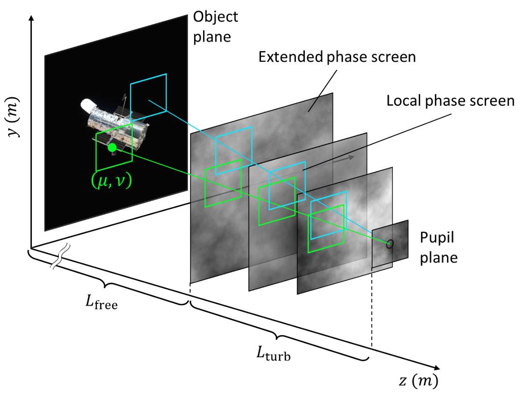
The propagation medium is modeled as a sum of two layers: the vacuum over distance \(L_{free} \ (=250 \ \text{km})\) and the atmospheric turbulence over disntace \(L_{turb} \ (=50 \ \text{km})\). The turbulence layer is modeled as a set of discrete phase screens that is computed based on the modified von Karman statistics.
The object is modeled as a set of many point sources. From each point source, a spherical wave is emitted and propagted through the vacuum and the phase screens until the center of the telescope pupil. By repeating this procedure, we will compute the spatially-variable PSFs for all sample points on the object.
Point spread function
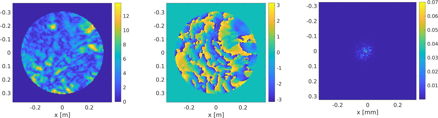
The figure above shows one example of the output obtained from the numerical wave propagation:
- Left: irradiance of the propagated wave field.
- Middle: phase of the propagated wave field. The fringe pattern is generated because of the collimation by a lens.
- Right: PSF obtained from the propagated wave field. The PSF spreads over a region with diameter of \(\sim 0.1 \) mm.
Degraded image of LEO object
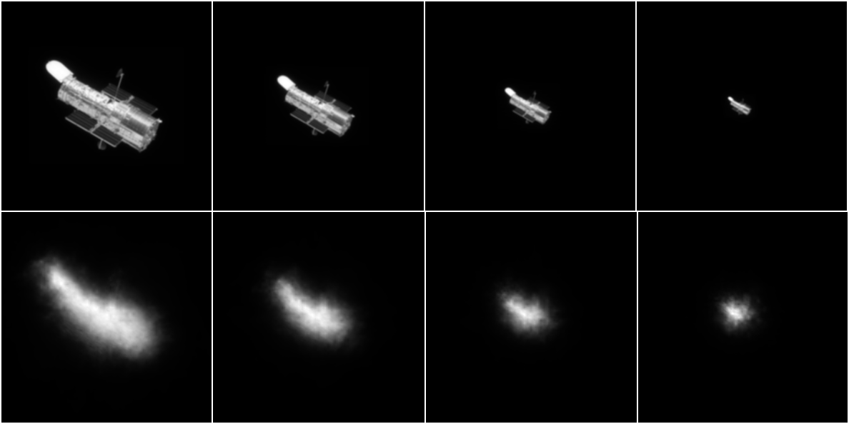
The observed image is computed by superposition integral of the original object image and the PSFs.
- Top: images of HST simulated without atmopsheric turbulence.
- Bottom: images of HST simulated with atmospheric turbulence.