Space object characterization
Overview
Most space objects around the Earth are too remote to be resolved by even the most advanced telescopes. What's worse, the telescope images are often degraded by atmospheric turbulence. As a result, only available information is a time history of brightness with almost no spatial resolution, which is called a light curve.
The video below is a demo of light curve of a satellite on geosynchronous orbit. In the top panel, a red arrow indicates the sunlight direction, and a red dot on the Earth shows an observer in Tokyo. You can see that the light curve intensity on the bottom-right panel changes, according to the change of relative position of the satellite.
As you can see in this demo, a light curve depends on the shape, attitude, and surface properties of the object and relative positions with respect to the observer and the Sun. This implies that it may be possible to invert those unknown properties of space objects based on the light curve. This is the basic idea of light curve inversion technique, which is explored in my research.
"Reformulating Compressed Sensing to be used with SemiResolved Point Spread Function and Light Curves for Space Object Imaging: LEO". In: Proceedings of the AMOS Conference. (2022)
In this study, the atmospheric turbulence is used as an encription key that transforms an object image into a light curve. In most previous studies, a turbulence effect has been regarded as a noise source of astronomical images. However, this study turns "bad" into "good".
Simulation of optical imaging of space objects
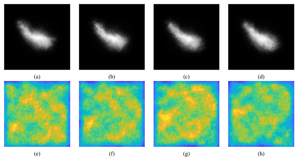
First, the imaging of space objects by telescope is simulated by numerical wave propagation under anisoplanatic condition. The images above shows four time frames of simulation results:
- Top: time sequence of degraded images of Hubble Space Telescope.
- Bottom: spatial distribution of optical disturbance, which is named point spread function map (PSF map).
Simulation of light curve
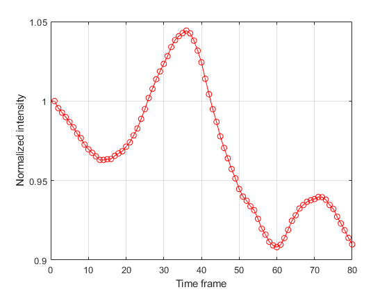
Light curve is simulated by summing up the pixel values of the simulated degraded image at each time frame. The image above shows one example of the light curve with 1 m/s of wind speed over 80 time steps. The horizontal axis shows the time step, and the vertical axis shows the normalized intensity of light curve. The light curve fluctuation is smooth and contiuous because the wind speed is relatively slow. For a faster wind speed, the light curve becomes more random and discontinuous.
Reconstruction of images from light curve
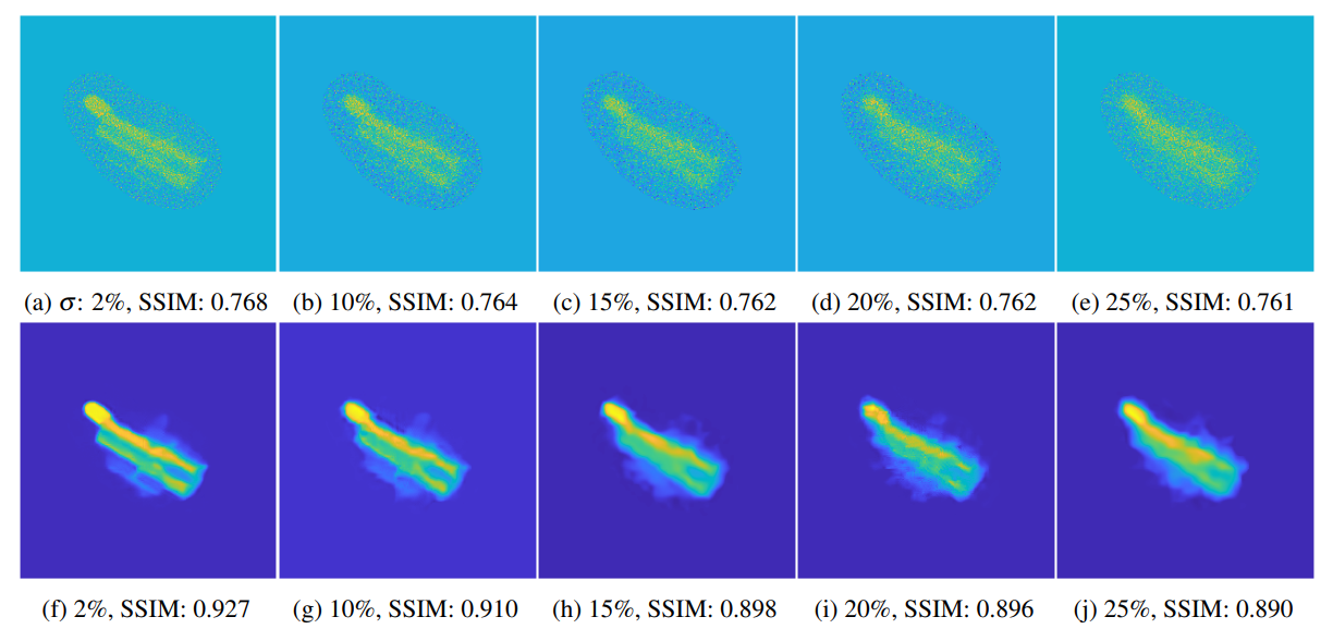
This study shows that the light curve measurement is strongly related to a technique called compressed sensing (CS). Compressed sensing is a signal compression theory that permits recovery of signals from massively downsampled signals by leveraging an encription key, sensing matrix. In this study, the PSF map is used as a sensing matrix, and a resolved space object image is recovered by a CS-solver. The images above shows the simulation results:
- Top: images recovered from light curve by solving Dantzig Selector.
- Bottom: images denosied by BM3D algorithm.
Funding information
This project has been supported by the U.S. Air Force Office of Scientific Research (AFOSR) under grants FA9550-19-1-0407 and FA9550-18-1-0154 DEF, under the name of Carolin Frueh."Compressed Sensing for Satellite Characterization: Shadowing as a Sensing Matrix". In: 8th European Conference on Space Debris. (2021)
This study shows that a shadow cast on a space object can be used as an encription key that helps us recover an unknown object geometry from its light curve. This shadow-based approach makes up for the drawback of the atmosphere-based approach. The problem of the atmosphere-based approach is that it does not work for objects in high orbits, because the light from those objects converges before reaching the atmosphere. In contrast, the shadow-based approach works for any orbits as long as the attitude motion generates nearly random shadow patterns.
Definition of "Net"
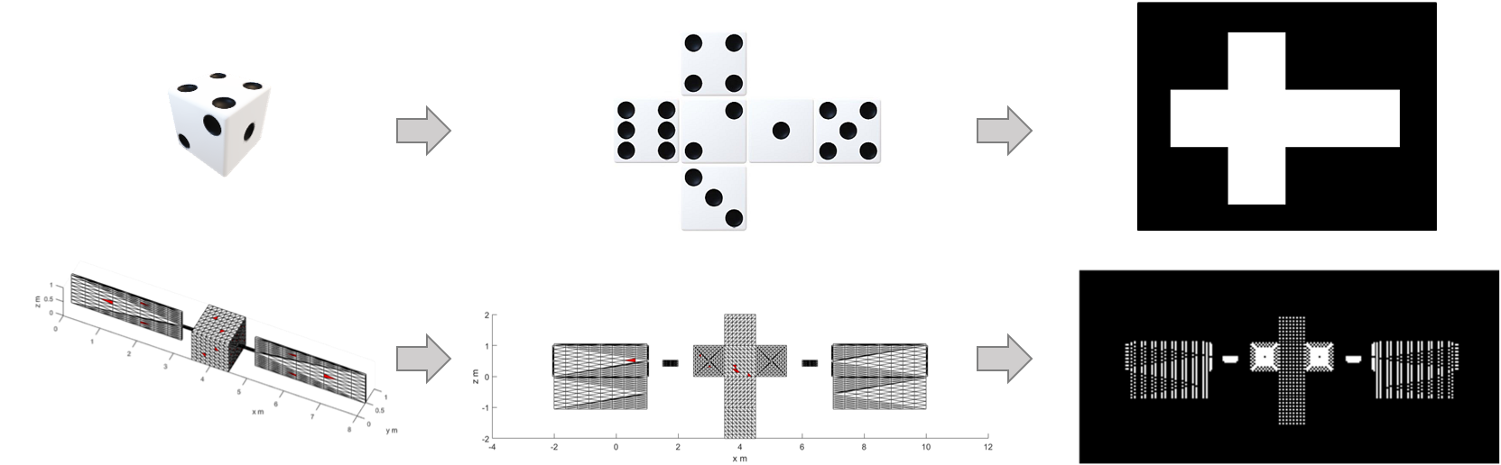
We need to define a new geometry that does not change regardless of attitude motion. This constantness is important because it is required by compressed sensing. In this study, we use a geometry called "net". The net is a 2D alignment of polygons that can be folded back to its original 3D shape. Examples for a dice and a satellite model are shown above. Our goal is to recover the net from the light curve measurement.
- Top: 3D models of dice (left) and satellite (right)
- Middle: net of the 3D models. We can form the 3D model by folding the net.
- Bottom: net image, which is simply a binarized net (1=facets, 0=background).
Shadow patterns on "Net" due to attitude motion
The video above shows how the motion of the space object changes the shadow pattern on the net, causing the fluctuation of the light curve intensity. Note that yellow=illuminated, black=shadow.
- Top-left: a box-wing satellite with attitude motion.
- Top-right: a light curve of the satellite.
- Bottom-left: a net of the satellite.
- Bottom-right: a net image of the satellite.
Reconstruction of "Net" from light curve
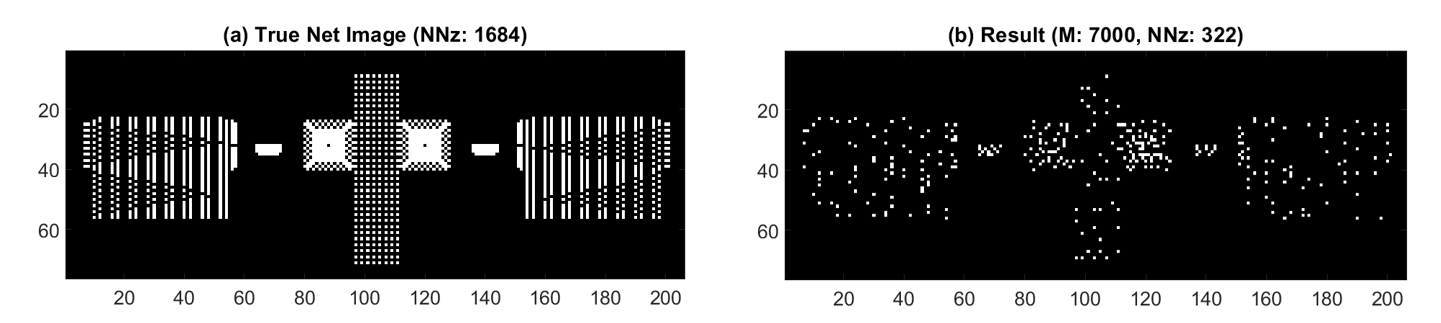
Light curve is generated for 7000 time steps by ray-tracing of the box-wing satellite model with vairous attitudes. Given the light curve and the shadow pattern, the net image is recovered by compressed sensing.
The figure above shows the recovered result of the net image (bottom) and the truth (top). The result is imperfect but still provides the overall shape of the true net. The imperfection is caused by the fact that the shadow pattern is not perfectly random and does not follow the Restricted Isometry Property (RIP) that is required in comressed sensing. However, at a careful look, you notice that the two components: the connecting rod and the side panel of the satellite, are recovered very accurately. This is probably because these components tend to have more random shadow pattern and follow RIP better.
Funding information
This project has been supported by the U.S. Air Force Office of Scientific Research (AFOSR) under grants FA9550-19-1-0407 and FA9550-18-1-0154 DEF, under the name of Carolin Frueh.